
Introduction: Embracing the Electrification Revolution, Redefining Mobility
A profound wave of electrification is sweeping global industries. From the AGVs (Automated Guided Vehicles) in logistics centers to the AWPs (Aerial Work Platforms) on construction sites and the zero-emission electric forklifts in warehouses, traditional hydraulic drive systems are progressively being replaced by cleaner, more efficient, and more intelligent electric motor drive systems.
Unlike the “brute force” of a hydraulic motor, an electric drive offers unparalleled precision control, instantaneous response, and superior energy efficiency. However, to convert the high-speed (typically 3000-6000 RPM) output of an electric motor into the high-torque, low-speed (typically 50-200 RPM) motion required by the wheels, we still rely on a trusted component: the planetary reducer.
The combination of an electric motor and a planetary gearbox forms the heart of the modern electric travel mechanism. However, the selection criteria for an electric drive are vastly different from those for a hydraulic one. Your focus shifts from displacement and pressure to voltage, power, duty cycle, and control systems. This guide will provide a comprehensive walkthrough of the selection process for an electric-driven travel mechanism.
Part 1: Why is “Motor + Planetary Reducer” the Golden Combination?
In electric drive solutions, it is theoretically possible to use a large-diameter, low-speed torque motor for direct drive. However, this solution is prohibitively expensive and bulky. Therefore, the “high-speed motor + high-ratio reducer” model has become the optimal solution that balances cost, efficiency, and size.
Why Choose a Planetary Reducer for Electrification?
- Perfect Match for High-Speed Input: Planetary gearboxes are naturally suited to connect to high-speed power sources. They can smoothly and efficiently handle inputs of several thousand RPM from servo motors or PMSMs.
- Unmatched Torque Density: This is the hallmark of a planetary gearbox. It can achieve massive reduction ratios (e.g., 50:1 or 100:1) in an extremely compact space, multiplying the motor’s limited torque tens of times over to propel heavy equipment.
- High Efficiency & Low Noise: Electric equipment places extreme demands on energy efficiency (battery life) and noise levels (indoor applications). High-precision planetary gearing (efficiency >95%) minimizes energy loss, while its smooth meshing ensures exceptionally low operational noise.
- Robust Load-Bearing Capacity: An electric travel mechanism must also support the full weight of the equipment. The robust bearing system within a planetary reducer (especially in wheel-hub drive designs) provides powerful radial and axial load-bearing capabilities.
Part 2: Deconstructing the Electric Travel Mechanism: The Three Core Components
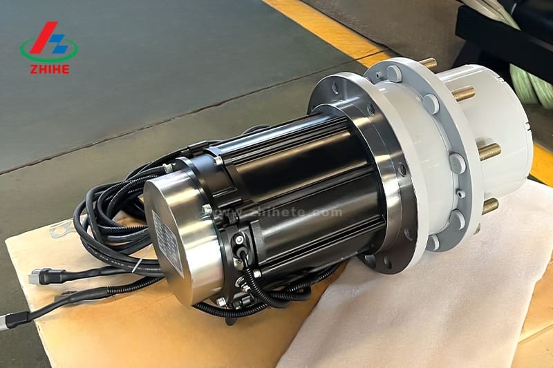
A complete electric travel drive assembly typically consists of three tightly integrated parts:
- The “Heart” – The Electric Motor: This is the power source. The most common types are Permanent Magnet Synchronous Motors (PMSM) or Brushless DC Motors (BLDC). They offer high efficiency, high power density, and a wide speed-control range.
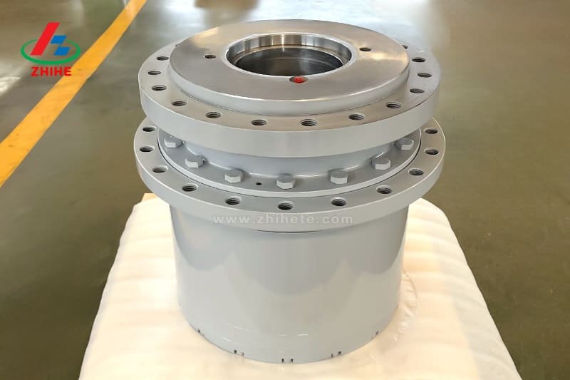
- The “Muscle” – The Planetary Reducer: This is the torque multiplier. It transforms the motor’s high-speed, low-torque output into the low-speed, high-torque force needed at the wheel.
- The “Brain” – The Controller/Driver: This component is absent in most hydraulic systems. The controller receives commands from the master control system (e.g., the AGV’s brain) and precisely regulates the motor’s speed, direction, and torque, achieving centimeter-level positioning and closed-loop speed control that is nearly impossible for hydraulics.
Note: When selecting, you must consider these three components as a single, integrated system.

Part 3: Key Technical Parameters for Selecting Electric Travel Drives
Forget the hydraulic terms “Bar” and “cc/rev.” We must now focus on the following electrical and mechanical parameters:
1. Rated Voltage
This is the first parameter and must match your equipment’s battery system.
- Common Standards: 24V, 48V (mainstream for AGVs, forklifts, AWPs), 80V, or even higher (for large electric construction machinery).
- Selection Advice: The voltage class directly dictates system current and cabling costs. It must strictly align with the vehicle’s electrical architecture.
2. Torque & Speed — The Core Calculation
This is the most complex step in the selection process. You must work backward from the “wheel-end” to the “motor-end”.
- Step 1: Determine Wheel-End “Demand”
- Required Torque ($T_{wheel}$): This is a calculation based on gross vehicle weight, rolling resistance, the maximum grade (e.g., a 15% ramp), and desired acceleration. The torque required for gradient climbing is usually the decisive maximum value.
- Required Speed ($N_{wheel}$): Determined by your desired maximum travel speed and the wheel diameter. $RPM = (Speed\ m/min * 1000) / (Wheel\ Diameter\ mm * \pi)$.
- Step 2: Select the Gear Ratio ($i$)
- The ratio is the bridge between “demand” and “supply.” You need to select a motor (e.g., 3000 RPM rated speed) and a ratio that meets the wheel speed requirement.
- $i \approx N_{motor} / N_{wheel}$
- Step 3: Verify the Motor’s “Capability”
- Once the ratio is set, calculate the required motor torque: $T_{motor} \approx (T_{wheel}) / (i * \eta)$ (where $\eta$ is the reducer efficiency, typically ~0.95).
- The motor you select must have a Rated Torque greater than this calculated value, and its Peak Torque must be able to cover the instantaneous maximum torque needed for acceleration or climbing.
3. Duty Cycle
This is a critically important yet often-overlooked parameter for motor selection. It determines the motor’s heat dissipation and lifespan.
- S1 (Continuous Duty): The motor runs at its rated load for long periods (hours), like a conveyor belt.
- S3 (Intermittent Duty): The motor cycles between “run” and “stop” periods, like an AWP’s travel or an AGV’s stop-and-go movements. S3 is typically noted as a percentage (e.g., S3 40%).
- Selection Advice: Most travel mechanisms are S3. If you use an S3-rated motor in an S1 application, it will quickly overheat and burn out. You must be honest about your operational profile.
4. Radial & Axial Load Capacity
The reducer’s output bearings must support the vehicle’s entire weight (radial load) and withstand immense side forces during steering (axial load).
- Selection Advice: Especially for AGVs with steerable wheels or AWPs that pivot in place, the axial load capacity is a key measure of the reducer’s robustness.
5. Integration & IP Rating
- Integration: Buying a pre-integrated “travel assembly” (motor, reducer, brake, and wheel as one unit) drastically reduces installation complexity, eliminates misalignment errors, and saves space.
- IP Rating: Motors and controllers are electronics; they are sensitive to water and dust.
- IP54: Suitable for dry, indoor warehouse environments.
- IP65/IP67: Necessary for AWPs that may be exposed to water or dusty outdoor environments.
Part 4: Application-Specific Selection Differences
| Application | Primary Focus | Key Requirement |
| AGVs / Warehouse Robots | Efficiency & Accuracy | High battery life, low noise, low-backlash reducers. |
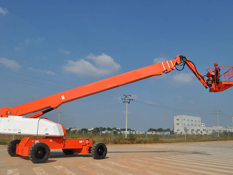
| Aerial Work Platforms (AWP) | Torque & Safety | Reliable electromagnetic brakes, S3 duty cycle, IP65+ rating. |
| Electric Forklifts | Durability & Shock Resistance | High S3 cyclic load capacity, robust construction against impacts. |
Part 5: Beyond Specs: The Value of Integrated Solutions & Engineering Expertise
In the era of electrification, a travel mechanism is no longer an isolated mechanical part; it is an integrated mechatronic system. The biggest challenge often lies in the perfect matching and integration of the motor, reducer, and controller.
The ZHIHE Advantage
This is where the value of a professional planetary transmission manufacturer becomes clear. Companies like ZHIHE, which not only manufacture high-precision planetary gears but also deeply understand how those gears must work in concert with electric motors, can provide an optimized integrated travel assembly. They ensure the reducer’s gear precision and bearing configuration are specifically designed for the high-speed input and S3 duty cycle of an electric motor.
Choosing a supplier with a deep engineering heritage in planetary technology, such as ZHIHE, means you aren’t just getting a product; you’re getting an engineered solution that guarantees your system runs efficiently, quietly, and reliably.
Conclusion: Choosing “Intelligent Legs” for Your Electric Equipment
The logic of selecting a travel mechanism has fundamentally changed in the shift from hydraulic to electric. A smart choice begins with a clear understanding of your vehicle’s electrical system (Voltage), its operating profile (S1/S3 Duty Cycle), and its performance needs (Torque/Speed).
Electric Travel Drive Selection Checklist:
- Define the Voltage Class (24V, 48V, etc.).
- Calculate the maximum wheel torque (for climbing) and top wheel speed.
- Select an initial gear ratio based on a target motor speed.
- Verify the required rated and peak torque for the motor.
- Assess your Duty Cycle (S1 vs. S3).
- Check that the reducer’s radial/axial load capacity can support the vehicle weight and steering forces.
- Determine the required IP Rating and integration strategy.
Choosing a highly integrated, well-matched electric travel drive is the key to keeping your equipment competitive in the age of electrification.


